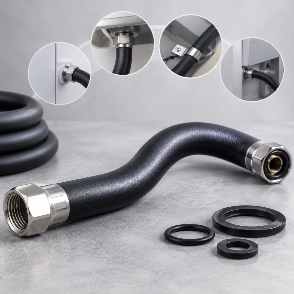
Direct answer: an appliance connector hose should be specified from its installed relationship between the pump, tub, dispenser or valve—not from its free-state length alone. For a useful quotation and validation plan, define the connections, molded geometry, relative movement, operating exposure and acceptance conditions together.
This documentation-first approach also reflects a broader industry emphasis on making specification information accessible and maintainable [1]. A separate supplier guide for a different hose category uses a step-by-step selection framework based on service conditions [2]. Neither source establishes performance for an appliance connector, but both reinforce a practical procurement principle: application inputs must be explicit before a hose can be evaluated.
Start With the Two Mating Components
For Appliance Connector Hoses, label the ends consistently as A and B and identify every branch. Record each interface profile, inside diameter and available clamping length in millimetres. This matters because the ends may have different diameters, beads or clamp zones, and reversing them can produce an incomplete specification.
Include drawings of the mating components and show the hose in its installed orientation. Clearly separate smooth sealing and clamping areas from sections intended to flex. Locate molded branches and fixing features relative to surrounding parts rather than describing them as isolated details.
Define Geometry in the Installed Position
- Offset: State the required displacement between connection centre lines.
- Leg lengths: Dimension the portions that control routing and assembly.
- End clocking: Specify rotational orientation in degrees where the ends or branches are not aligned.
- Clamp access: Show the space available for installing and servicing each clamp.
- Clearance: Identify nearby cabinet panels, pumps, tubs, valves and other possible interference points.
A physical sample can help communicate the shape, but it does not replace installed component positions and their tolerances. If the surrounding assembly controls the offset, those assembly dimensions should accompany the sample.
Account for Movement and Exposure
Explain whether either connected component moves relative to the cabinet or to the other connection. State the direction and expected amount of relative motion, along with the surrounding clearance. The flexible section and the sealing zones serve different purposes, so movement requirements should not be inferred from appearance alone.
Document the water and detergent or cleaning-agent cycle, including the applicable temperature and time conditions. Also identify pressure or vacuum transients and the units used. These are project inputs for compound and design review, not proof of universal detergent resistance or a guaranteed operating envelope.
Agree on Acceptance Before Tooling
Turn general expectations into reviewable conditions. The project inquiry should address installed fit, clamp retention, leakage and movement tests. State the setup, cycle and pass/fail criteria for each requirement. Appliance-specific aging or material-document requirements should also be identified rather than assumed from the molded shape.
A connector drawing defines the part; an installed-position package defines whether that part can be evaluated for the assembly.
Buyer Inquiry Checklist
- Provide drawings for the hose and both mating components.
- Label ends and branches, including profiles, diameters and clamping lengths.
- Dimension offsets, leg lengths and end clocking.
- Show installed orientation, clamp access and surrounding clearance.
- Quantify relative component movement.
- Describe the water, detergent and cleaning cycle with temperature and time.
- State pressure or vacuum transients with named units.
- Define fit, retention, leakage and movement acceptance conditions.
- List required material documents and project-specific validation criteria.
Know the Limits of the Specification
A connector shape alone does not imply potable-water approval, universal chemical resistance or compatibility with a named appliance model. Compound, tolerances, operating conditions and acceptance criteria must be agreed for the individual project. The next step is therefore to submit the installed-position package and acceptance plan for engineering review, rather than requesting a hose from a sample or free-state dimension alone.
Research sources
External sources provide background. Search results are not Google search volume or verified performance specifications for Xinwei products.
- [1] Industry News — 2026-11-10T00:00:00Z — estimated source date
- [2] High-Pressure Steel Wire Wrapped Rubber Hose — 2026-11-10T00:00:00Z — estimated source date