Define the intake circuit
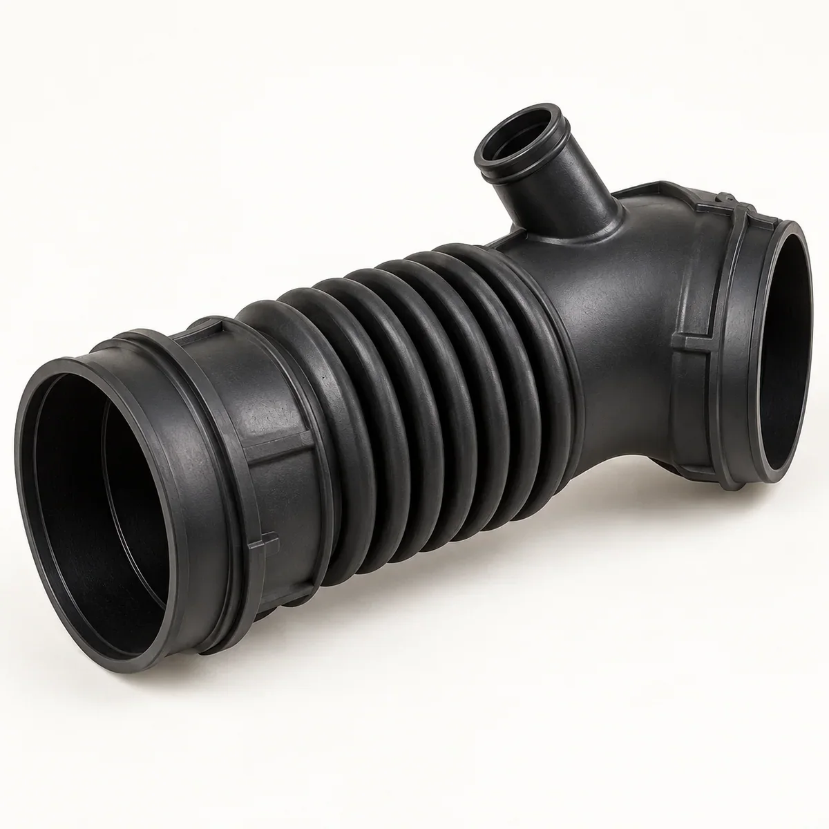
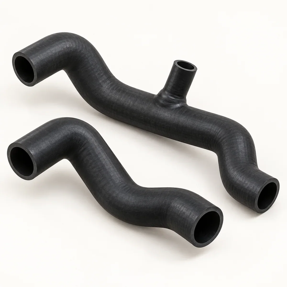
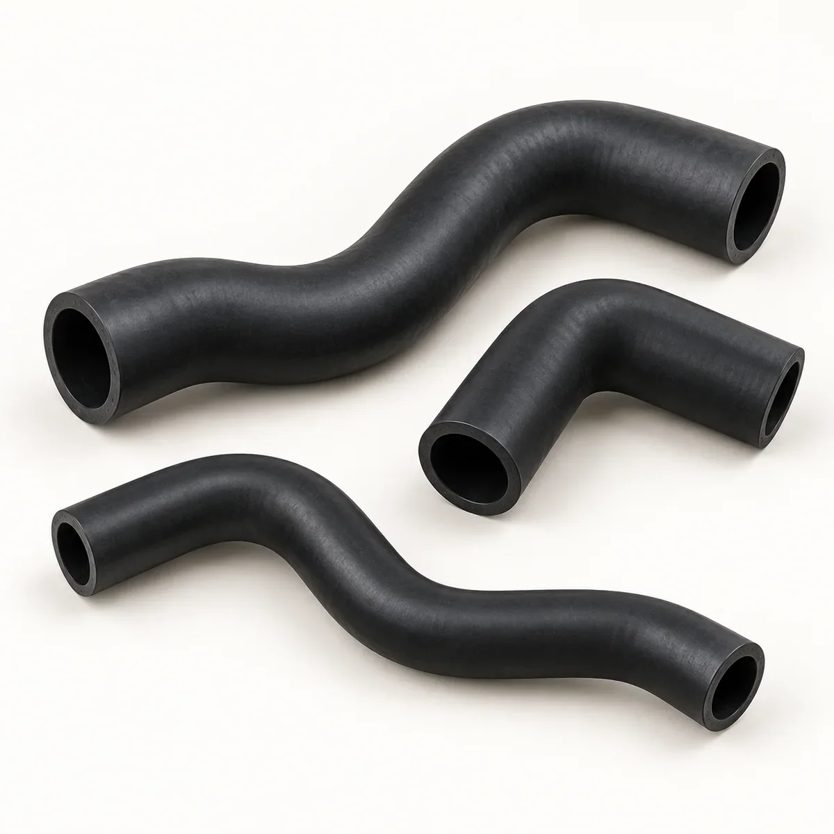
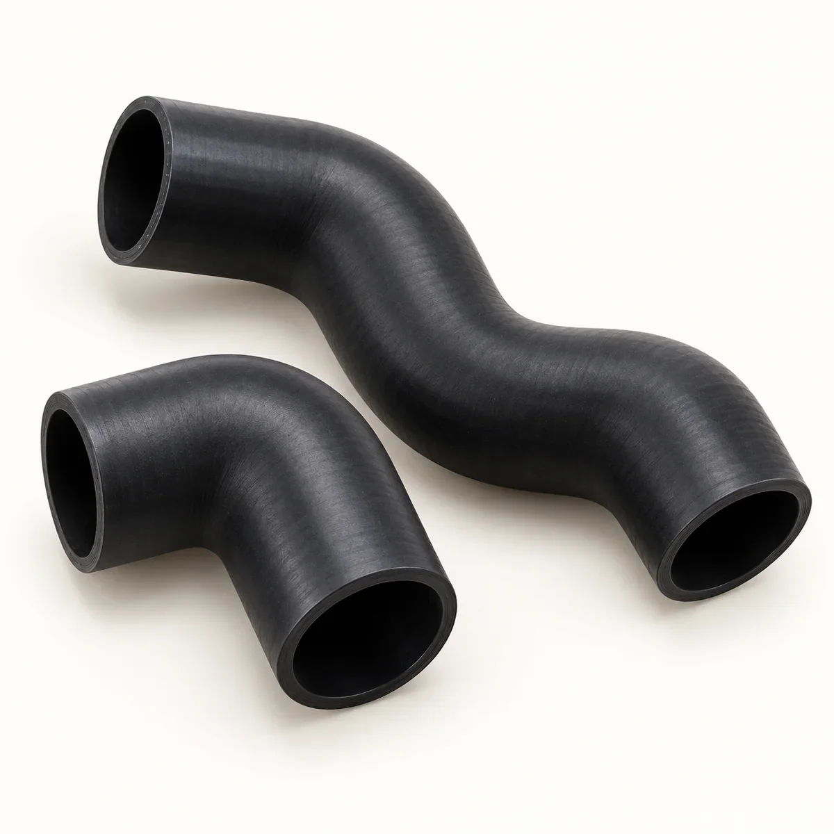
Identify the hose location in the air path and whether it sees only suction or also positive pressure. Include sensor branches, resonator connections and mounting features on the drawing. A visually similar duct may route air differently or interfere with the surrounding assembly.
- Dimension the inlet and outlet shapes separately.
- Show relative end rotation in three dimensions.
- Mark bracket, port and sensor locations.
Review movement and collapse conditions
State vacuum level, any pressure event, air temperature and external heat exposure. Record engine or equipment movement relative to the fixed air box. If a corrugated section is proposed, define the movement envelope and surrounding clearance rather than treating corrugation as proof of flexibility or collapse resistance.
Limit the claimed service
An intake duct is not automatically a turbocharger charge-air hose, fuel hose or emissions-certified part. Fit, sealing, airflow and durability acceptance should be defined for the actual assembly.
Prepare your inquiry
- Air-system location and route drawing.
- End fittings, clamps, ports and mounting details.
- Vacuum/pressure and thermal/motion conditions.
- Required system validation and quantity.
Buyer questions
Is an intake hose suitable for boosted charge air?
Only a construction evaluated for that pressure and thermal duty should be considered. State the circuit clearly.
Can ports be located from a photo?
Use the photo as context and provide dimensioned positions and orientations relative to defined datums.
Related project families
Engineering reading
General references and scope
These references explain general engineering or regulatory context. They are not Xinwei finished-product specifications, test results or compliance evidence.
- Wire Inserted Green Stripe Coolant Hose — Illustrates that reinforcement, bend radius, dimensions and application limitations belong to an identified hose construction. No Gates rating, standard compliance or construction is claimed for Xinwei.