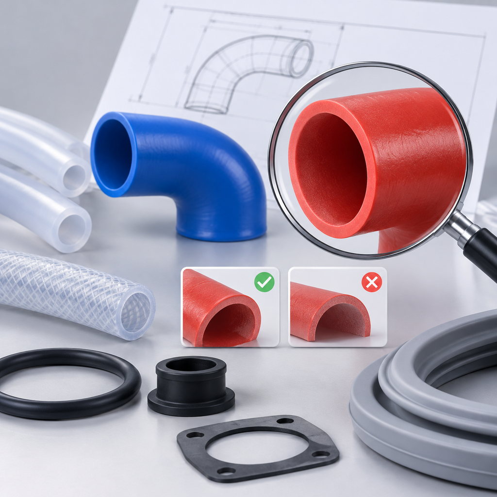
A common mistake in custom rubber purchasing is to begin with a photograph, a familiar material name or a single dimension. A part may look like a hose, elbow, sleeve, boot or gasket, but its suitability depends on what it must do in the completed assembly.
A useful inquiry therefore separates six questions: What is the function? Which surfaces or components interface with the part? What media and cleaning conditions apply? What loads, movement or pressure occur? What evidence is required? How will the finished assembly be accepted?
The product references below are project families, not universal performance specifications. Their fields help buyers prepare requirements for review. They do not, by themselves, establish service life, pressure capability, regulatory compliance, chemical compatibility or compatibility with a named machine.
Start with function, not appearance
Two clear silicone tubes can have different tasks. One may transfer fluid without repeated compression, while another may operate inside a peristaltic pump. Likewise, a molded elbow, appliance connector and automotive coolant elbow may have similar shapes but face different interfaces, media and validation requirements.
Before requesting a quotation, write one sentence describing the part’s job. Examples include transferring an ingredient, repeatedly compressing in a pump head, draining an appliance, protecting a moving joint or sealing a bolted flange. This statement establishes the selection boundary and prevents a visually similar part from being treated as automatically equivalent.
Food-contact silicone hose projects
Pump tubing: define the compression system
Silicone Pump Tubing Projects should be identified by the pump interface as well as the fluid path. Record the pump or head model, specified tube size and occlusion setting where available. Specify ID, OD, wall thickness, concentricity requirement, active pumping length and end connections together.
Operation also needs definition: speed, duty cycle, temperature, inlet and outlet pressure, fluid identity, viscosity context and cleaning exposure. A measurable trial should state the required flow or dose, allowable variation, duration, visible-damage criteria, leakage criteria and replacement threshold.
A material document does not establish pump life or dosing behavior. Those questions require an agreed trial using the relevant tube, pump head, fluid and settings.
Food-contact documentation is a separate review. It should identify the proposed formulation or finished tube and the intended food and cleaning exposure. Pump performance should not be inferred from food-contact evidence, and food-contact suitability should not be inferred from a pumping trial.
Transfer tubing: specify the complete route
Silicone Transfer Tubing Projects cover straight tubing for defined transfer tasks. Buyers should specify ID, OD, length, tolerances, measurement state, fittings, retention method and installed bends. The duty should distinguish gravity feed, suction and positive pressure rather than using the general term transfer hose.
Describe the actual food or ingredient, relevant composition context, contact time, frequency, temperature and cleaning cycle. If wall transparency is required for visual inspection, state that as a functional requirement rather than treating clear appearance as evidence of food suitability.
Formed elbows: geometry does not prove cleanability
Formed Silicone Hose Elbow Projects may be considered where a straight tube cannot follow the installed route. Define the angle, centerline radius, leg lengths, end clocking, installation orientation and surrounding equipment. Dimension both ends independently, including unequal diameters, offsets, insertion lengths and fitting details.
A smooth-looking bend is not proof of drainage or cleaning performance. State the food, contact conditions, cleaning agents, concentrations, time, temperature, disassembly conditions and orientation during cleaning. Fit and leak checks can then be agreed for the finished construction.
Braided hose: reinforcement is part of the construction
Braided Silicone Hose Projects require the buyer to define pressure, vacuum, temperature, routing, movement, support, fittings and retention. The inner layer, reinforcement, outer layer and end treatment belong to one reviewed construction; braid should not be treated as an automatic pressure rating.
Working-pressure, burst, vacuum, leakage and fitting-retention conditions are separate requirements to agree. Evidence should be checked against the proposed finished hose, including its contact surfaces and assembly materials, rather than assumed from documentation for unreinforced tubing.
Appliance components: define every installed interface
Sleeves and short connectors are different buying tasks
Appliance Sealing Sleeves can bridge a short gap, locate around a spigot or seal a penetration. The inquiry should identify whether the sleeve carries fluid or seals around another component. Provide its ID, OD, length, lips or flanges, mating profiles, tolerances, axial position, interference or gap, assembly direction and permitted aids.
Appliance Connector Hoses connect defined pumps, tubs, dispensers or valves. Label each end and branch consistently, especially where diameters, beads or clamp zones differ. Show offset, leg lengths, end clocking, clamp access, surrounding clearance and relative component movement.
The selection mistake is to copy a free-state length or one fitting diameter. Acceptance should instead address installed fit, clamp retention, leakage and movement under the specified water, detergent, pressure and temperature cycle.
Drain hose: map the discharge path
Appliance Drain Hoses require both end profiles, insertion lengths, clamping areas, free length, installed route and support points. Identify height changes, flexible or corrugated sections, abrasion areas and repeated movement.
Record water temperature, detergent, cleaning chemicals, suspended debris and pump-discharge or gravity-drain conditions. Drain service should not be assumed equivalent to a pressurized inlet, drinking-water line or food-contact hose. Agree end-retention, leakage, drainage and routing checks for the actual assembly.
Door gasket: the machine opening is the interface
Washing Machine Door Gaskets interact with the tub, front panel and door. Supply those interface profiles, retaining-wire or clamp locations, installed folds, orientation marks, ports, drainage locations and movement clearances.
A machine photograph or similar outline is not enough to establish compatibility. Define water, detergent, bleach or cleaning-agent identities, concentrations, temperatures and exposure times. Installation, door closure, drainage and assembled leakage checks should be appliance-specific.
Automotive hose projects: describe the circuit
Complex molded routes need controlled geometry
Custom Molded Automotive Hoses are relevant when a route includes multiple bends, branches, offsets or diameter changes. Provide a controlled drawing or three-dimensional model, label each end and branch, identify mounting datums and state which features cannot change.
The circuit determines the review. Specify the exact fluid or air service, contamination, pressure or vacuum cycle, temperature, movement, fittings and clamps. If reinforcement, inserts or multiple layers are requested, list them as construction requirements for feasibility review. A vehicle name alone does not establish fit or release status.
Vent and intake routes require different exposure questions
Breather and Vent Hoses should be specified by circuit function, vapor composition, possible oil mist, condensate, cleaning exposure, differential pressure, temperature and orientation. Mark branches, high and low points, valves or restrictors and any kink, drainage or permeation criteria that the project must evaluate.
Air Intake Hoses require separate inlet and outlet geometry, route, end clocking, datums, ports, brackets and sensor connections. State whether the circuit sees suction only or also positive pressure, together with airflow requirements, air temperature, external heat, vibration and relative movement.
An intake duct should not be assumed suitable for boosted charge air, and a vent hose should not be assumed suitable for fuel immersion or an emissions-controlled application. Those boundaries must be established through the project specification and required validation.
Coolant elbow: specify both the shape and cooling cycle
Coolant Elbow Hoses need End A and End B dimensions, connection lengths, fitting-bead details, elbow angle, centerline radius, leg lengths, wall requirement and installed clearance. Identify the coolant formulation or mixture, temperature cycle, pressure transients, cooldown vacuum and approved clamps and fittings.
The external shape does not reveal the compound or reinforcement. A coolant elbow also should not be treated as suitable for oil, fuel, steam or charge-air duty without a separate construction and exposure review.
Molded seals: define retention, motion and both-side exposure
Plugs close openings, but not always for the same reason
Rubber Stoppers and Plugs may provide temporary protection, repeated operator access or a permanent closure. Define the receiving bore, tolerance, edge condition, insertion depth, permitted projection, taper dimensions, flange or handle, insertion method and removal method.
If pressure retention is required, state the pressure differential and the relevant acceptance test. Interference or a tight appearance alone does not establish safe retention. Also define exposure, temperature, removal frequency and cleanliness requirements.
Diaphragms require information from both chambers
Rubber Diaphragms separate chambers or transmit movement. Specify the active diameter, thickness profile, clamping bead or flange, compression stop, stroke direction, displacement, cycle frequency and any insert or attachment.
List the media, temperature and pressure on each side, including transients, cleaning fluids and vented air. Dimensions and hardness alone do not demonstrate functional equivalence. Assembly, leakage and flexing should be evaluated under the intended cycle.
Bellows and boots must work throughout their travel
Rubber Bellows and Dust Boots need minimum, nominal and maximum installed lengths, lateral offset, angular movement, maximum envelope, surrounding clearances and both attachment details. State whether the purpose is dust or splash protection, or whether fluid containment is also required.
Record external oils, cleaning agents, debris, temperature and any venting need. A boot that looks correct at one position may interfere or overstress at another, so the acceptance plan should cover the complete motion rather than only an extended free-state sample.
Grommets control a panel interface and a pass-through interface
Rubber Grommets should be defined by the panel-hole contour, panel thickness, pass-through diameter or range, groove dimensions, flange geometry, insertion direction and available tool access. State whether the task is edge protection, routing support, retention or an environmental seal.
A soft grommet does not automatically provide strain relief, electrical insulation or an ingress rating. If those functions matter, define a complete assembly test and acceptance criteria.
Gaskets: specify the joint, not only the loose part
Cover and frame gaskets depend on closure geometry
Silicone Cover Gaskets require the lid and rim profiles, perimeter, groove, assembled gap, compression stops, retention method and removal or cleaning frequency. Specify the medium and cleaning schedule. Silicone, color and hardness do not by themselves establish food-contact suitability or chemical compatibility.
Rubber Frame Gaskets need the complete perimeter, inner and outer contours, corner radii, section, hinge and latch locations, closure gap and joint policy. State whether the design uses a groove, flat land or temporary retention. If an ingress or leakage requirement applies, define the complete enclosure test rather than assigning a rating to the loose gasket.
Flange and flat gaskets require assembly information
Rubber Flange Gaskets should be specified with the flange standard and edition or a dimensioned drawing, facing type, gasket ID, OD, thickness, bolt holes, bolt circle, flange material, hardware and approved tightening procedure. Include the fluid, concentration, temperatures, working pressure, transients and test conditions with named units.
A flange class is not a pressure rating for an unspecified rubber gasket, and a torque value for another gasket and joint should not be transferred without an approved assembly procedure.
Flat Rubber Gaskets require a controlled two-dimensional outline, thickness and tolerance, openings located from datums, sealing-land information, surface condition and fastener layout. If an old gasket is measured, distinguish its used, compressed condition from the intended free-state nominal thickness.
Adhesive backing, if requested, should be treated as an additional material and functional requirement. Define whether it contacts the medium and whether clean removal matters.
A practical purchasing sequence
- Name the function. State what the part transfers, seals, protects, connects or separates.
- Control every interface. Provide mating-part profiles, tolerances, fitting details, clamp zones, grooves and assembly datums.
- Describe the installed state. Include route, orientation, compression, movement, support, clearance and drainage.
- List exposure conditions. Identify media, concentrations, contact times, temperatures, cleaning agents and contamination.
- Quantify the duty. State pressure, vacuum, transients, flow, speed, stroke, cycle frequency or retention forces as applicable.
- Define evidence scope. Ask which formulation, specimen, finished construction and intended use each requested document covers.
- Agree acceptance criteria. Specify dimensional, fit, leakage, retention, movement, pumping, drainage or assembly tests before release.
Questions to ask before placing an order
- Does the drawing show every mating interface and installed orientation?
- Are dimensions provided in a defined measurement state and unit?
- Have free-state dimensions been separated from assembled gaps, interference and compression?
- Are pressure, vacuum, temperature and time conditions stated rather than implied by the application name?
- Does the cleaning description include the agent, concentration, temperature, duration and disassembly condition?
- Does each requested report identify the proposed formulation or finished construction it covers?
- Are functional acceptance tests tied to the real assembly rather than only to a loose sample?
- Have unsupported assumptions about service life, certification, named-model fit or cross-application equivalence been removed?
Clear next step
Prepare a concise inquiry package containing the function statement, controlled drawing, mating interfaces, installed layout, exposure schedule, operating duty, evidence requirements and acceptance plan. Then select the project family that matches the actual task. This approach does not predetermine suitability, but it gives the supplier and buyer a defined basis for reviewing construction, documentation and validation without relying on shape, material name or appearance alone.