Material compatibility questions often begin with a material name: “Is silicone suitable?” or “Can this rubber handle detergent, coolant or oil?” For a custom hose, tube, gasket or molded seal, that is not enough information to make a purchasing decision. Compatibility depends on the proposed formulation, finished construction, actual media, contact cycle, temperature, mechanical duty, cleaning process and acceptance method.
A useful inquiry therefore describes the application before requesting a material recommendation. The buyer should also separate three decisions: whether the material is appropriate for the exposure, whether the geometry functions in the installed assembly, and whether the finished product has been validated against agreed criteria. None of these decisions automatically proves the other two.
Start with the contact conditions, not the material name
Create an exposure list that covers every substance likely to contact the part. Include the main process medium, incidental contaminants, cleaning chemicals, lubricants and fluids used during assembly. For food-transfer projects, identify the actual food or ingredient rather than writing only “food grade.” Relevant context can include fat or alcohol content, viscosity, contact duration and the destination market for documentation review.
Temperature should be recorded as a cycle, not a single convenient number. State normal, peak, cleaning and shutdown temperatures, with durations in degrees Celsius. A brief cleaning exposure and continuous process exposure may present different selection questions.
The same principle applies to pressure and movement. State whether the system is gravity-fed, under suction, pressurized or exposed to transients. For seals and molded parts, identify compression, stretch, flexing, insertion and removal conditions. These inputs are selection criteria, not published performance claims for any product family.
Questions to answer before discussing compatibility
- What contacts each surface of the finished part?
- What are the concentration, contact time, frequency and temperature?
- How is the part cleaned, rinsed, drained and stored?
- Does the part experience pressure, vacuum, compression, movement or repeated flexing?
- Which formulation, finished construction and use conditions must the requested evidence cover?
- What test result will determine whether the proposed part is accepted?
Food-contact tubing: four different buying tasks
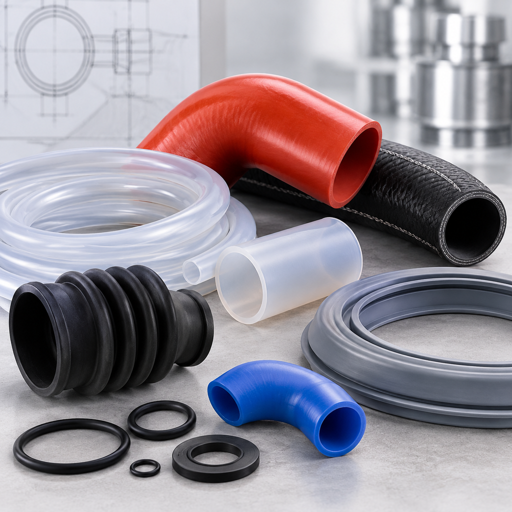
Silicone tubing and hose projects can look related while requiring different project questions. A buyer should first decide whether the part transfers fluid, operates inside a pump head, resolves a constrained bend or requires reinforcement.
Silicone Transfer Tubing Projects concern straight transfer routes. Specify ID, OD and length together, then define the food or ingredient, contact cycle, cleaning chemicals, pressure or vacuum, fittings and required flow. Transparent appearance does not identify the formulation or establish suitability. A raw-material statement also should not be treated as a finished-tube result without checking its scope.
Silicone Pump Tubing Projects add a repeated compression interface. Record the pump and head model, specified tube size, ID, OD, wall thickness, active pumping length, speed, duty cycle, occlusion setting where available, operating temperature and inlet and outlet conditions. Ordinary transfer tubing with a similar bore should not be assumed to produce equivalent pumping behavior.
The pump trial should have measurable criteria: fluid identity, required flow or dose, allowable variation, trial duration, visible damage checks, leakage criteria and the planned replacement threshold. Food-contact evidence and pumping performance remain separate reviews. A material document does not establish pump life or dosing behavior.
Formed Silicone Hose Elbow Projects address routes that a straight tube cannot follow satisfactorily. Provide the bend angle, centerline radius, leg lengths, unequal end sizes, end clocking and installed orientation. Also show surrounding equipment and explain how the elbow is cleaned and drained. A smooth-looking bend does not prove cleanability or drainage.
Braided Silicone Hose Projects require the reinforcement and end assembly to be treated as part of the construction. Identify suction, positive pressure or both; working and transient conditions; vacuum; temperature; bend space; movement; fittings; and clamp or crimp requirements. Braid does not automatically create a pressure rating. Pressure, burst, vacuum and fitting-retention tests must be separately specified for the proposed assembly.
Appliance parts: define the interface and the installed cycle
Appliance projects often combine water, detergents, heat, movement and compact assembly spaces. The material discussion must be tied to the exact component function.
Appliance Sealing Sleeves may bridge a short gap, fit around a spigot or seal a penetration. State whether the sleeve carries fluid or seals around another component. Supply both mating profiles, tolerances, installed position, interference or gap range, assembly method, movement and cleaning exposure. The sleeve ID should not simply be copied from a fitting OD without defining the intended fit.
Appliance Connector Hoses connect defined pumps, tubs, dispensers or valves. Label every end and branch, particularly when diameters, beads or clamp zones differ. Provide offset, leg lengths, clocking, clamp access, relative component movement, water and detergent cycle, and pressure conditions. A free-state sample alone may not define installed fit.
Appliance Drain Hoses should be specified around the discharge route. Show both ends, free length, installed routing, supports, height changes, abrasion areas and flexible or corrugated sections. Record water temperature, detergent, debris, cleaning chemicals and pump or gravity conditions. Drain service should not be assumed equivalent to a pressurized inlet or drinking-water application.
Washing Machine Door Gaskets interact with the tub, front panel, door, retaining components and moving drum. Define those interfaces, orientation, drainage ports, folds and movement clearances. The exposure specification should name detergent, concentration, water temperature, bleach or cleaning agents and duration. Compatibility with a named machine cannot be concluded from a photograph or similar outline.
Automotive hose inquiries: identify the circuit first
Automotive hose geometry does not identify the medium or operating duty. Two visually similar parts may serve different circuits and need different constructions.
Custom Molded Automotive Hoses are appropriate for branched, offset or multi-bend routes that require controlled CAD and a dimensioned drawing. Label every end and branch, identify the circuit medium, and provide pressure or vacuum cycles, temperature, motion, fittings, clamps and requested construction features. CAD can define geometry, but it cannot replace the circuit and validation requirements.
Breather and Vent Hoses require a precise description of the gas, vapor, condensate, oil mist and cleaning exposure. Mark high and low points, branches, orientation, valves and restrictors. If permeation or emissions criteria apply, state them as explicit project requirements. The word “breather” does not establish fuel immersion compatibility, low permeation or regulatory approval.
Air Intake Hoses need the intake-system location, vacuum level, possible positive-pressure events, air temperature, external heat, component movement, ports and mounting features. Define the corrugated section’s movement envelope if one is proposed. An intake duct should not be assumed suitable for charge-air, fuel or emissions-controlled service without a separate construction and validation review.
Coolant Elbow Hoses require both end interfaces, bend centerline, leg lengths, clamp access and installed clearance. Identify the coolant and concentration, continuous and peak temperatures, pressure transients and cooldown vacuum. The outside elbow shape does not establish reinforcement, and coolant service should not be extended to oil, fuel, steam or charge-air duty without review.
Molded seals: compatibility includes deformation and both-side exposure
For molded seals, the fluid list is only one part of compatibility. Retention, compression, travel, insertion and repeated movement may control whether a material and geometry work together.
Rubber Stoppers and Plugs can be temporary dust closures, removable stoppers or permanent sealing plugs. Define the receiving bore, edge condition, insertion depth, pressure differential and removal frequency. If pressure retention is required, specify and validate it directly; a tight appearance is not evidence of safe retention.
Rubber Diaphragms require media and temperature information for both sides. Provide the clamping design, active flexing area, stroke, frequency and pressure on each side over time. Dimensions and hardness alone cannot establish functional equivalence, fatigue life or pressure capability.
Rubber Bellows and Dust Boots should be evaluated through their complete motion. Supply minimum, nominal and maximum installed lengths, lateral or angular movement, package diameter, surrounding clearances and both attachment ends. Distinguish dust or splash protection from fluid containment, and identify any venting requirement.
Rubber Grommets control both a panel interface and a cable or tube interface. State panel thickness, opening profile, pass-through dimensions, insertion direction, movement and exposure. Edge protection, environmental sealing, strain relief and electrical insulation are separate functions and should not be inferred from a soft molded pass-through.
Gaskets: evaluate the complete joint
Gasket compatibility cannot be separated from compression, closure geometry and joint condition. A suitable compound can still be used incorrectly if the gap, surface, retention or tightening method is not controlled.
Silicone Cover Gaskets need the lid and rim sections, assembled gap, compression stops, retention method and removal cycle. Name the contact medium and cleaning process. Silicone, color and hardness do not by themselves establish food-contact suitability, chemical compatibility or closure behavior.
Rubber Frame Gaskets add corners, hinges, latches and potentially uneven closure gaps. Specify the complete perimeter, corner radii, section, retention method and whether a seam is permitted. If water or dust exclusion is required, define the complete enclosure test rather than assigning an unsupported rating to the loose gasket.
Rubber Flange Gaskets require the exact flange standard and edition or a controlled drawing, facing type, dimensions, hardware, process fluid, temperature and pressure conditions. A flange class is not a pressure rating for an unspecified rubber gasket. Tightening values must come from the approved procedure for the actual joint.
Flat Rubber Gaskets should be defined by a dimensioned outline, nominal free-state thickness, openings, sealing land, surface condition and fastener layout. A thicker gasket should not be assumed to correct a damaged or misaligned joint. If adhesive backing is requested, include it in the exposure and removal review as an additional material.
Separate documentation from functional validation
Ask what each document identifies. Does it cover a formulation, a specimen, an unreinforced tube, a formed part or the complete finished assembly? Does it address the intended market and contact conditions? Additional layers, braid, exposed ends, fittings, adhesive or inserts may change the evidence scope.
Then create a separate functional validation plan. Depending on the application, it may include fit, leakage, flow variation, drainage, pressure, vacuum, fitting retention, pull-off, insertion force, movement, closure or flex testing. The conditions and pass criteria should be written before samples are assessed.
A compatibility decision is strongest when the exposure specification, product construction, document scope and functional test all describe the same proposed part and application.
A practical next step for the buyer
Prepare one inquiry package containing a revision-controlled part or assembly drawing, a complete media and cleaning table, operating cycles, mating interfaces, installed orientation and explicit acceptance criteria. Mark unknowns rather than replacing them with assumptions.
For each requested product, ask the supplier to identify the proposed construction, unresolved feasibility questions, evidence available for that construction and the sample tests needed before release. This approach does not promise suitability in advance. It creates a traceable process for deciding where a product may be considered and where a different construction, test plan or application boundary is required.